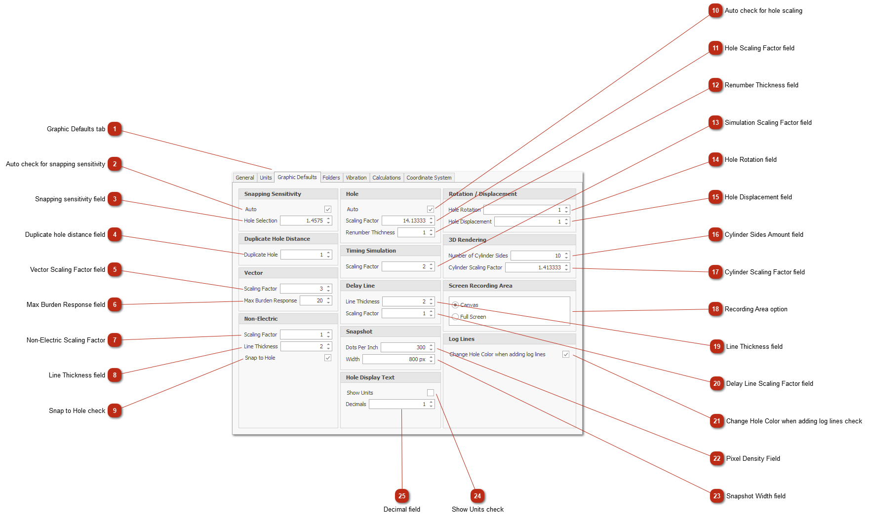
Graphic Defaults tab
|
|
 Auto check for snapping sensitivityAutomatically works out the sensitivity value for snapping lines to holes.
|
|
 Snapping sensitivity fieldValue indicating the snapping distance from a line to a hole.
|
|
 Duplicate hole distance fieldSet the distance between holes that identifies duplicate holes.
|
|
 Vector Scaling Factor fieldScale factor for visual display of a vector object on the design canvas.
|
|
 Max Burden Response fieldThe maximum burden response value that the vector can go to when using the visual scroll bars on top of the vector.
|
|
 Non-Electric Scaling FactorScale factor for visual display of a Non-Electric connection object on the design canvas.
|
|
 Line Thickness fieldVisual thickness of the Non-Electric connection line in the design canvas.
|
|
 Snap to Hole checkNon-Electric connection will snap to closest hole using snapping sensitivity.
|
|
 Auto check for hole scalingAutomatically adjust the hole scaling factor.
|
|
 Hole Scaling Factor fieldValue used to factor the size of the displayed hole.
|
|
 Renumber Thickness fieldVisual line thickness of the line displayed when renumbering holes.
|
|
 Simulation Scaling Factor fieldSize scaling when simulating "Fire Blast"
|
|
 Hole Rotation fieldValue in degrees applied when rotating holes using keyboard arrow keys.
|
|
 Hole Displacement fieldDistance value applied when moving holes with keyboard arrow keys.
|
|
 Cylinder Sides Amount fieldAmount of sides in the 3D generated cylinder representing holes.
The more sides, the more smoothly the holes appear. Also takes longer to render.
The less sides, the less smooth the holes appear. Quicker to render.
|
|
 Cylinder Scaling Factor fieldThe scaling factor size of the 3D generated hole.
|
|
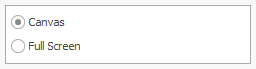
 Recording Area option-
Canvas - Screen records the design area only. -
Full Screen -Screen records the entire application.
|
|
 Line Thickness fieldDisplay thickness of line on the design.
|
|
 Delay Line Scaling Factor fieldScale factor size for visual display of the delay line.
|
|
 Change Hole Color when adding log lines checkChanges the hole fill color when adding AXXISTM log lines.
Helps to see visually when a hole is added to the line.
|
|
 Pixel Density FieldDPI value for snapshot images.
|
|
 Snapshot Width fieldSets the width of the snapshot image.
|
|
 Show Units checkWhen selected will display the unit measurement after the displayed text.
The displayed text on the design canvas like "Hole Depth", will display "12 m" or if measurement system is imperial display " 12 feet".
This option can be selected in the layers dock panel as well.
|
|
 Decimal fieldSets the amount of decimal numbers after the decimal symbol to be displayed.
This value can also be changed in the layers dock panel.
|
|